INDUSTRIAL BURNERS
Is it really the cheapest burner to choose?
When we talk about burners, we are led to believe that one product is worth the other and that basically the only thing that matters in the end is the price or the brand. Nothing more wrong! In fact, such a conclusion is paid for as soon as the plant comes into operation. In addition to the price of a system, the two elements to consider are:
- The quality of the product. It is different to use, for example, lances made of drawn tube in AISI 310 steel rather than tube in AISI 304 of the welded type as often the market offers. In the same way, having the end part in AISI 310 cast steel rather than in AISI 304 steel is quite different. The different duration of the two products certainly justifies the higher price of one over the other.
- The control of the combustion air fuel ratio. This condition is completely excluded in the analysis of one burner with respect to another. This is a fundamental relationship that must be able to be fixed by the plant operator in such a way as to limit as much as possible the amount of combustion air based on the functional geometry of the furnace. It is clear that excess combustion air inlets significantly reduce the efficiency of the combustion system. Heating excess air does not lead to any benefit, on the contrary, a greater consumption of fuel. It is customary to think that a mechanical lever system that links the fuel delivery valve to the air control valve is enough to solve the problem. Nothing could be more wrong: Adjusting the air flow, compressible fluid, by means of a mechanical valve is practically impossible. There is no proportion between the degree of opening of a valve and the amount of air introduced. So how to have a constant perfect proportion of the set air / gas ratio? The mechanism is simple even if more expensive: a mass flowmeter is applied to the fuel duct, the value that emerges is analyzed, it is sent to a PLC that provides the command suitable for the frequency variator serving the motor combustion air. Think, on a 300 ton / day brick plant that requires a theoretical consumption of methane gas equivalent to 12,000 cubic meters, the entry of 200,000 cubic meters of combustion air compared to perhaps 120,000 cubic meters of combustion air sufficient for combustion leads to greater consumption of methane gas of the order of 1,600 cubic meters which in a year become 480,000 cubic meters of methane gas.
These are the first simple considerations that should guide the choice of one burning system over another one.
DUCT AIR GAS GENERATORS
GAS BURNERS
OIL BURNERS
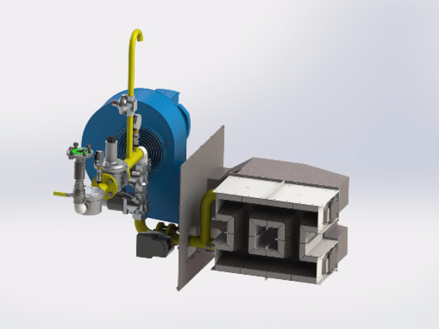
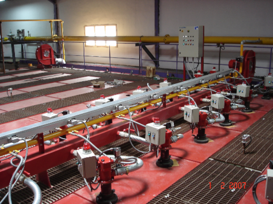
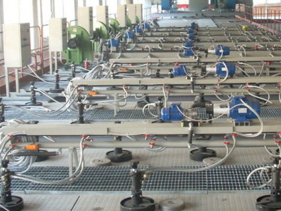
SUPERTEC produces a wide range of burners and feeders for the heavy clay industry which are capable of meeting all technical requirements and safety standards. Their implementation is linked both with the area of application and with the used fuel.
The distinction between the names: burner and feeder indicates a machine which is able to provide directly to the phenomenon of combustion as it is composed of a combustion chamber with a spark plug, which means it is a machine whose purpose is to inject the fuel, or a mixture of fuel and air inside the kiln. In that mentioned case, the ignition takes place within the kiln in the areas where the temperature is higher than the ignition temperature of the fuel.
Therefore, our range of products composed of gas burners and pet coke, coal and biomass, heavy oil, gas, hybrid feeders can be employed in the ignition phase of the kiln (burners), in the preheating zone of the kiln (burners), in the firing zone of the kiln (burners and feeders).
Particular attention is given to the enclosures if the rods inserted inside the feeding firing openings of the kiln. They are divided into two types:
Burner rod: it is composed of an element in stainless drawn tube steel having an outer diameter of 100 mm which is installed in the lower part a cone-shaped toe made of silicon carbide having a wall thickness of 5.00 mm able to resist the firing temperatures gained within the burner.
Feeder rod: it is composed of an element made of stainless drawn tube steel having an outer diameter of 35 mm and wall thickness of 1,5. mm. A steel toe made of refractory steel and having walls thickness of mm. 3,5 is welded at the bottom, able to resist the temperature inside the kiln and the possible chemical aggression due to the substances included in the clay.
In the section below, you can choose the type of the burner or a feeder you are looking for.
FOR MORE INFORMATION
SUPERTEC SRL Sede legale VIA CARLO LAVERONI 37- 14100 ASTI (ITALY) Codice Fiscale e Partita IVA: 00460890759 UFFICIO DELLE IMPRESE DI ASTI N. REA 113775 CAPITALE SOCIALE VERSATO Euro 50.000,00 info@supertecweb.com - supertec@pec.it